KOENIG EXPANDER® SERIES MB 700 – OVERVIEW
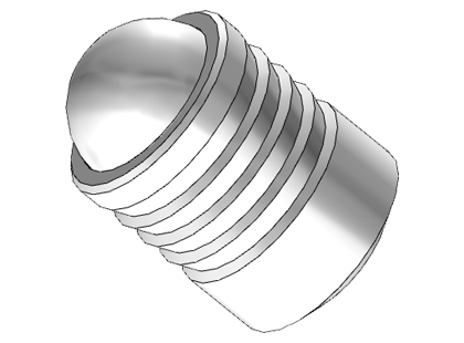
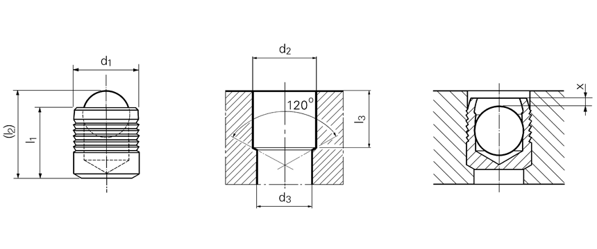
Series MB 700 KOENIG EXPANDER® plugs effectively seal drilled holes. These parts feature a serrated sleeve which expands as the ball is inserted, enlarging the part to the needed size and sealing the hole. For installation, push-style expanders require a hole drilled with a counter bore. If you are unsure if the MB 700 expander sealing plug series is the right component for your application, use our Product Selector to identify the best KOENIG EXPANDER part for your specifications.
 Series MB 700 KOENIG EXPANDER® plugs effectively seal drilled holes. These parts feature a serrated sleeve which expands as the ball is inserted, enlarging the part to the needed size and sealing the hole. For installation, push-style expanders require a hole drilled with a counter bore. If you are unsure if the MB 700 expander sealing plug series is the right component for your application, use our
 Material:
Sleeve: Stainless Steel DIN 1.4305 Ball: Bearing Steel, Heat Treated
Product SpecificationsPressure PerformanceTechnical DownloadsVideo
| Product Number | d1 | l1 | (l2) ~ Ref. | d2 +0.10 / -0 | d3 Max | l3 min. | x ±0.2 | (s) ~ Ref. | Packaging Unit | Weight in gram/pcs. | 3D CAD |
|---|---|---|---|---|---|---|---|---|---|---|---|
| MB 700-030 | 3 | 3.6 | 4.6 | 3 | 2.2 | 3.4 | 0.4 | 1.2 | 100 / 1000 | 0.17 | View CAD |
| MB 700-040 | 4 | 4 | 5.2 | 4 | 3.3 | 3.8 | 0.2 | 1.5 | 100 / 2000 | 0.34 | View CAD |
| MB 700-050 | 5 | 5.5 | 7 | 5 | 4.3 | 5.3 | 0.4 | 2.0 | 100 / 2000 | 0.68 | View CAD |
| MB 700-060 | 6 | 6.5 | 8.6 | 6 | 5.3 | 6.3 | 0.4 | 2.5 | 100 / 2000 | 1.17 | View CAD |
| MB 700-070 | 7 | 7.5 | 10.1 | 7 | 6.4 | 7.3 | 0.4 | 3.0 | 100 / 1000 | 1.9 | View CAD |
| MB 700-080 | 8 | 8.5 | 11.6 | 8 | 7.4 | 8.3 | 0.3 | 3.5 | 50 / 1000 | 2.84 | View CAD |
| MB 700-090 | 9 | 10 | 13.5 | 9 | 8.4 | 9.8 | 0.4 | 4.0 | 50 / 500 | 4 | View CAD |
| MB 700-100 | 10 | 11 | 15.1 | 10 | 9.4 | 10.8 | 0.4 | 4.5 | 50 / 500 | 5.47 | View CAD |
| MB 700-120 | 12 | 13 | 17.8 | 12 | 10.6 | 12.8 | 0.4 | 5.5 | 50 / 250 | 9.31 | View CAD |
| MB 700-140 | 14 | 15 | 20.4 | 14 | 12.7 | 14.5 | 0.4 | 6.35 | 50 / 250 | 14.72 | View CAD |
| MB 700-160 | 16 | 17 | 23.4 | 16 | 14.7 | 16.5 | 0.6 | 7.0 | 25 / 100 | 22 | View CAD |
| MB 700-180 | 18 | 19 | 26.3 | 18 | 16.7 | 18.5 | 0.6 | 8.0 | 25 / 100 | 31.34 | View CAD |
| MB 700-200 | 20 | 22 | 30 | 20 | 18.7 | 21.5 | 0.8 | 9.0 | 25 / 100 | 44.24 | View CAD |
| MB 700-220 | 22 | 25 | 34 | 22 | 20.7 | 24.5 | 0.8 | 10.0 | 25 / 50 | 58.61 | View CAD |
Dimension in millimeters
| Series MB 700 mm |
Base Material of the Installation | ||||||
|---|---|---|---|---|---|---|---|
High Strength Steel ETG-100 / 44SMn28 AISI 1144 |
Case Hardened Steel C15Pb / 1.0403 AISI 10L15 |
Ductile Cast Iron EN 1563: GJS-600-3 ASTM A536: 80-60-03 |
Gray Cast Iron EN 1561: GJL-250 ASTM A48: NO.35 |
Aluminum-Alloy AICu4Mg1 / EN AW-2024-T3 AA: 2024 T4/T6* |
Aluminum-Alloy AIMgSiPb / EN AW-6012-T6 AA: 6012-T6 |
Cast Aluminum-Alloy G-AISi7Mg / EN-AC-42100 ASTM/UNS: A356 |
|
| Ø 3 – 10 | 1400 bar / 20300 psi 450 bar / 6500 psi |
1200 bar / 17400 psi 380 bar / 5500 psi |
|||||
| Ø 12 – 22 | 1150 bar / 16700 psi 350 bar / 5100 psi |
900 bar / 13000 psi 280 bar / 4100 psi |
|||||
| Proof Pressure Test – Ⓑ Max. allowable Working Pressure = Nominal Pressure *SFC KOENIG’s North American Engineering Department utilizes 2024-T4/T6 as a test base material. |
|||||||
Operation
Technical Information
- Design Guidelines – wall thickness / distance from edge; required installation lengths, roundness tolerance, and conicity of the bore – view page or downloadable PDF
- Anchorage Principle – view page or downloadable PDF
- Galvanic Corrosion – view page or downloadable PDF
- Technical Information – test pressure, base material / installation requirements, pressure performance – view page or downloadable PDF
- Hardness Conversion Table – view page or downloadable PDF
- Quality Certificates