KOENIG EXPANDER® SERIES CV 588 – OVERVIEW
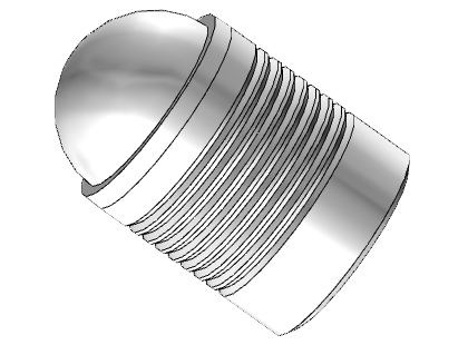

KOENIG EXPANDER® Series CV 588 plugs effectively seal drilled holes. These parts feature a serrated sleeve which expands as the ball is inserted, enlarging the part to the needed size and sealing the hole. For installation, push-style expanders require a hole drilled with a counter bore. If you are unsure if the CV 588 expander sealing plug series is the right component for your application, use our Product Selector to identify the best KOENIG EXPANDER part for your specifications.
 KOENIG EXPANDER® Series CV 588 plugs effectively seal drilled holes. These parts feature a serrated sleeve which expands as the ball is inserted, enlarging the part to the needed size and sealing the hole. For installation, push-style expanders require a hole drilled with a counter bore. If you are unsure if the CV 588 expander sealing plug series is the right component for your application, use our
 Material:
Sleeve: Stainless Steel (316) ASTM A580, Passivate, QQ-P-35C Ball: Stainless Steel, AISI 316, Wax Film Lubrication (Diameter Dependant)
Not all items in stock – MOQ and production lead times may apply
Product SpecificationsPressure PerformanceTechnical DownloadsVideo
| Product Number | d1 | l1 | (l2) ~ Ref. | d2 +0.10 / -0 | d3 Max | l3 min. | x ±0.1 | (s) ~ Ref. | Packaging Unit | Weight in gram/pcs. | 3D CAD |
|---|---|---|---|---|---|---|---|---|---|---|---|
| CV 588-040 | 4 | 4 | 5.2 | 4 | 3.3 | 3.8 | 0.2 | 1.4 | 100 / 1000 | 0.36 | View CAD |
| CV 588-050 | 5 | 5.5 | 7 | 5 | 4.3 | 5.3 | 0.2 | 1.9 | 100 / 1000 | 0.76 | View CAD |
| CV 588-060 | 6 | 6.5 | 8.6 | 6 | 5.3 | 6.3 | 0.2 | 2.3 | 100 / 1000 | 1.28 | View CAD |
| CV 588-070 | 7 | 7.5 | 10.1 | 7 | 6.2 | 7.3 | 0.2 | 2.8 | 100 / 1000 | 2 | View CAD |
| CV 588-080 | 8 | 8.5 | 11.7 | 8 | 7.2 | 8.3 | 0.2 | 3.4 | 100 / 1000 | 2.96 | View CAD |
| CV 588-090 | 9 | 10 | 13.7 | 9 | 8.2 | 9.8 | 0.2 | 3.7 | 100 / 1000 | 4.31 | View CAD |
| CV 588-100 | 10 | 11 | 15.2 | 10 | 9.2 | 10.8 | 0.2 | 4.2 | 100 / 500 | 5.88 | View CAD |
Dimensions in millimeters
| Series CV 588 mm |
Base Material of the Installation | ||||
|---|---|---|---|---|---|
|
High Strength Steel
ETG-100/44SMn28 AISI 1144 |
Ductile Cast Iron
EN 1563: GJS-600-3 ASTM A536: 80-60-03 |
Ductile Cast Iron (Dura-Bar®)
EN 1563: GJS-450-10 ASTM A536: 65-45-12 |
Aluminum-Alloy
AICu4Mg1 / EN AW-2024-T3 AA: 2024 T4/T6* |
Cast Aluminum-Alloy
G-AISi7Mg/ EN-AC-42100 ASTM/UNS: A356 |
|
| Ø 4 – 9 | 1000 bar / 14500 psi 350 bar / 5000 psi |
||||
| Ø 10 | 860 bar / 12500 psi 280 bar / 4000 psi |
||||
| Proof Pressure Test – Ⓑ Max. allowable Working Pressure = Nominal Pressure *SFC KOENIG’s North American Engineering Department utilizes 2024-T4/T6 as a test base material.
|
|||||
Operation
Technical Information
- Design Guidelines – wall thickness / distance from edge; required installation lengths, roundness tolerance, and conicity of the bore – view page or downloadable PDF
- Anchorage Principle – view page or downloadable PDF
- Galvanic Corrosion – view page or downloadable PDF
- Technical Information – test pressure, base material / installation requirements, pressure performance – view page or downloadable PDF
- Hardness Conversion Table – view page or downloadable PDF
- Quality Certificates