TECHNICAL INFORMATION - KOENIG RESTRICTOR
SFC KOENIG provides several restrictor options for different application requirements, and customers can select the restrictor’s orifice size. This allows you to have complete design control – CV expansion and threaded restrictors are custom-made to meet your orifice performance requirements. As with any component in your system design, there are many technical factors to consider. This is one method for calculating orifice diameter for the SFC KOENIG restrictor products.
- This equation was derived by rearranging Bernoulli’s Equation and using a Coefficient of Discharge (CD).
- The Coefficient of Discharge (CD) accounts for pressure losses resulting from factors such as orifice geometry, turbulence near the orifice hole, the length of the orifice hole, and flow dynamics.
- This equation for calculating the restrictor orifice diameters should be used as reference only. SFC KOENIG recommends that you perform testing in the actual application environment to determine the flow constant.
- This equation is intended as a guide for fluid applications only; it is not applicable for gas flow applications.
Metric
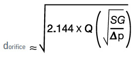
To calculate restrictor orifice diameter in mm:
To calculate restrictor flow rate in mm:
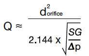
Where:
dorifice > Orifice diameter, measured in mm
Q > Fluid flow rate, measured in liters/minute
Δp > Fluid pressure difference across the restrictor, measured in bar
SG > Specific gravity of the fluid
2.144 > Constant = Unit conversion factor x CD
Please use our online flow rate calculator and orifice size calculator.
+ Flow Rate Calculator – mm
+ Orifice Size Calculator – mm
Metric
To calculate orifice length in mm:
L = (Ø x 0.207) + t
L = length of orifice (mm)
Ø = orifice diameter (mm)
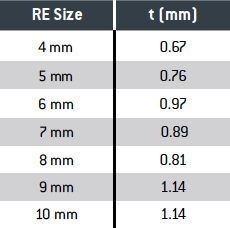
t = see chart below
Tolerance: +/– ((. x 0.021) + 0.13) mm